Model Builders Inc Blog

How a scale model helps envision and sell a gas processing plant.

Posted by Hal Chaffee on Mon, Mar 23, 2015 @ 11:41 AM

UOP had an investor meeting coming up and wanted to make a great impression showing the advantages of their prefabricated gas processing plant. UOP is the only manufacturer that makes a prefab one and it consists primarily of seven skids that can be trucked to the site. They also wanted to use this model for sales presentations and tradeshows. 

The UOP advantages are that the prefab gas processing plant can be made much more cost effectively in advance in a factory and there is little final assembly once the seven skids are shipped to the client's site. Furthermore quality control in the factory is much easier to manage than in the field.  UOP's competitors build  gas processing plants on site which takes far longer and their construction time is much more exposed to weather delays. 

UOP Gasification Plant Model

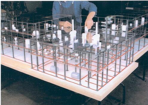
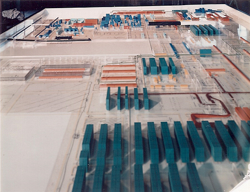
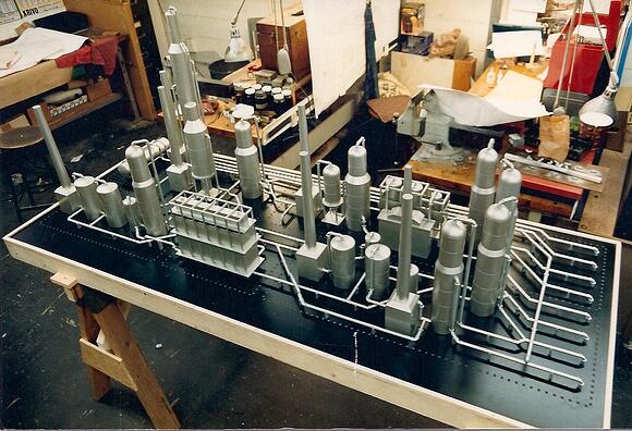
UOP prefabricated gas processing plant 1:48 scale model 25" long X 25" wide.

To have a real impact with investors and potential clients UOP wanted them to easily envision the prefabrication concept and how it went together. If they could pick up each of the seven skids to assemble or disassemble them by hand that would be very engaging and memorable. Furthermore clients would be able to see the key components in each skid. This is an effective way to relate to what each skid does and where it goes.

The model makes for quicker and easier comprehension of the entire plant than walking through the real one. Furthermore  the real prefabricated gas processing plant is too big to take to a tradeshow (or potential client) and most potential clients are not located near one of the installed prefabricated gas processing plants.

What were the keys to getting this model fabricated to meet UOP's short deadline and to be as effective as possible in generating sales? 

(1) Choose the right model maker.

Hire a professional model making firm with experience - in this case one that makes process models for heavy industry like oil, gas and nuclear models. This firm would know where to get the special materials necessary and have the expertise to help design and fabricate the model in about four weeks. For this model UOP hired Model Builders, Inc. in Chicago.

(2) Provide the information the model maker needs to build from right away.

UOP drawings were needed to build from and they were needed fast. Model Builders, Inc. suggested that only pdfs of some of the drawings were needed.  It would have taken more time and expense if the model maker had to get familar with the UOP CAD drawings since it takes a while (often several days) to get familiar with the many CAD assemblies and parts drawings.

The UOP Director of Corporate Communications recognized that the model maker needed the pdfs right away and put the key UOP engineer in Oklahoma in touch with the model maker. That same day the engineer was able to send out all the needed dimensioned drawings as pdfs.

(3) Choose the scale.

 The 1:48 scale was the right one for an engaging hands on demonstration and for transport in a personal vehicle if necessary. Furthermore a scaled flatbed truck was put on the model to help the viewer get a clearer idea of how big the skids were by comparison.

(4) Determine the level of detail.

One of the things about models is that viewers are often attracted to them when they are highly detailed. The details draw them in. With this model even the UOP designer was impressed with the detail accuracy. This is particularly helpful to the sales effort when UOP can discuss with potential buyers what each skid does and the component parts that do that.

Gas processing plant model

(5) Engage the viewer in creative ways.

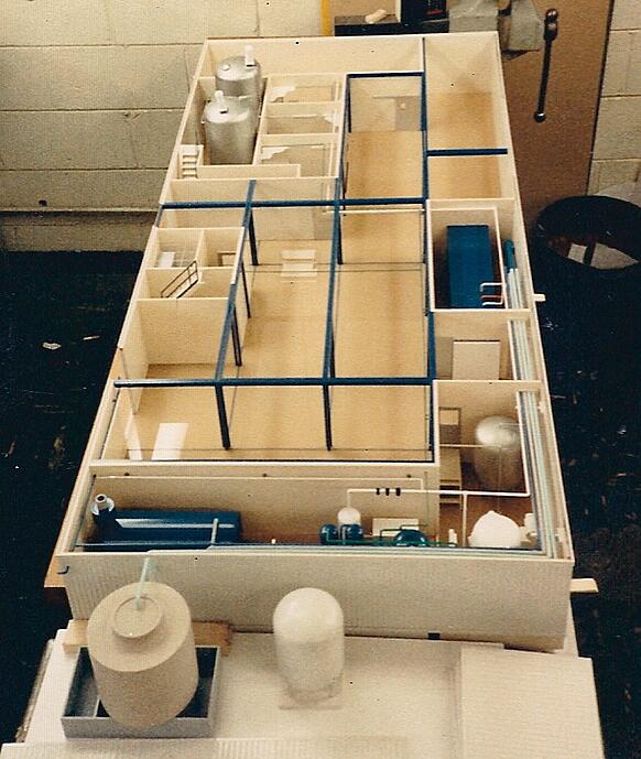
UOP had Model Builders, Inc. make the seven skids as loose units that can be assembled and disassembled by hand on a simple base with a plan view of the site on top. That meant each model skid could be picked up by hand and assembled or disassembled in the appropriate location on a scaled drawing. The drawing was bonded to the top of the 1" thick 25" X 25" base board.

Prefab Gasification Plant model

The stairway next to the right hand and the crosswalk next to the left finger are each connected with magnets for quick and easy assembly.


(6) Use durable materials.

ABS plastic is a very durable material and is the primary material used in this model. Futhermore the bonding liquid chemically welds the parts together.

In contrast acrylic is brittle and sometimes cracks or breaks. Vibrations during shipping and handling, below-zero temperatures and other adverse conditions could cause breakage or the acrylic glue joints could come apart.

(7) Make the model easy to pack and unpack.

The cutouts in the thick foam make packing and protecting the parts from damage simple.

Plant 

UOP gas processing plant model case.
The flat base with plan view is below the parts seen here. The truck is in the silver box.

How effective was the model at the investor's meeting? It was so effective UOP decided to order a second one to keep at the home office for potential customer presentations.

Model Builders, Inc. is known for helping manufacturers, industrial designers, institutions and individuals go from idea to reality. Take the next step by contacting us at Model Builders, Inc., 773-586-6500 or info@modelbuilders.net .


Tags: industrial scale models, site model, plant layout model, architectural model, model, product model, engineering model, product models, industrial scale model, tradeshow product models, trade show product models, process model, plant layout models, scale model

To make a plant layout model what does the model maker need from you?

Posted by Hal Chaffee on Thu, Jul 18, 2013 @ 06:52 PM

To quote and build a plant layout model the model maker needs information from you. With your answers to the following eight questions you can get a quote and timetable for a plant layout model that best meets your requirements.

1) What do you need a model of?

Does the plant model reprsent one product production line, a number of product lines, a distribution center, a process like an oil refinery with multiple buildings, tanks, piping and other structures? Is it an interior model only or does it include the site outside the building?

Plant engineering studies often use a plant layout model to help analyze different equipment configurations and layouts. An existing or proposed facility may be limited in space and determined by an architectural structure. Equipment models, block or detailed, may be used to represent the different types of equipment. The model equipment depictions can be moved around in the facility until the best layout is determined. In office areas plant layout models help determine how to divide office space and show other floor space options.

Many companies use a physical plant layout model in the process of optimizing the entire plant design including electrical, water, hydraulic and HVAC before construction starts. This engineering model provides a three dimensional view of the current design which acts as a focal point for communication among all of the engineers and other personnel involved.  Normally the model pays for itself by reducing or eliminating misunderstandings, omissions and reducing drawing requirements. 

A plant layout model is particularly helpful where there is a lot of complex piping. The piping can be color coded with industry standard colors to make it quicker to understand. If there are errors in the piping drawings they are discovered when a physical model is made and that saves time and money when the real piping is installed.

Plant Layout Searle

Pharmaceutical multi-story interconnected plant layout planning model

Sometimes a plant layout model of a large site is used to explain a process like water treatment to customers or the public so they can more easily visualize all of the buildings and tanks as well as their interrelationship. 

 2) What is the purpose of the model?

 If the model maker knows the purpose of the model you may get suggestions that improve the model to better achieve the purpose. For instance arrows on the equipment or floor may help in clarifying the direction of travel in the production line.

-Production line with arrows

Conveyor direction of travel shown with arrows 

- Are you building a new production line and using the model to figure out an optimal equipment layout?

- Is the plant layout model for production training in a manufacturing plant?

- Is the model to give an overall view of a large production area to show potential customers?

- Is it a focal point for employee quality meetings?

- Is it a plant layout model for planning changes in the production line?

- Perhaps the model is to explain the best design features to your workers, managers or clients.

Let the model maker know the purpose and what is important to highlight on the model.

3) What is the scale?

You may or may not have figured out how big you want the model.  We find it quite helpful if the potential client has already printed out a plan view and some elevation views of the model in the scale they think they want it.  They may find some important details such as control panels, piping or handles are too small in the model scale they originally thought they wanted. We have noticed that a number of clients need to see the printed out views before they can be sure it is in the right scale for their use.

Common scales for plant layout models are 1:48, 1:100 and 1:200.  A lot of model structural parts, materials, architectural parts, vehicles, people, landscape detail, etc. is available in those scales. It often helps to have a scale person(s) or vehicle(s) in the model to make it easier to understand visually the model scale.

If there are railroad tracks in the model it is much less expensive if the model is in a standard railroad hobby scale.  1:87 scale is HO gauge which is the most popular railroad gauge, 1:160 is N gauge. and 1:220 is Z gauge. For larger scales track exists. 1:48 scale is O gauge and 1:24 scale is American gauge. Tracks in a few other large gauges exist. A lot of plant layout models are 1:100 scale which is close enough to HO gauge that HO gauge railroad tracks, railroad cars, vehicles, people and cars are often used in 1:100 scale models.

4) Do  you have drawings and if so in what format?

 Model cost estimates should be based on requirements that are well thought out before the fabrication of the model begins. To get a model quote it is helpful to have at a minimum pdfs or alternatively printouts in the desired model scale with plan and elevation views. A common CAD file format is .dwg or .dxf. but many other common CAD formats can be used. Photographs of the plant and equipment are also quite helpful in determining the quote.

If not available at the quote phase then before model fabrications begins the model maker needs any detailed drawings that may be available.  If you do not have a complete set of drawings it is helpful to provide a list of what is missing. The drawings should also be reviewed prior to giving them to the model maker to be sure that there are no earlier obsolete drawings included or obsolete file types like .CAL files.  We have seen projects where the quote had to be revised by up to 40 percent more because 400 out of about 1,000 drawings were obsolete earlier versions of the same drawing, were not needed to build the model or were missing.

5) Do you need explanatory labels, diagrams or lights?

A control board with labels on the side of the model could also light up specific machines, areas or builidngs in the model. Chase lights could be added to show the flow of a production process. See our earlier blog on a plant layout model with a control board and lights at http://modelbuilders.net/blog/bid/154286/This-waste-water-treatment-plant-layout-model-shows-how-it-works .

6) What type of base do you need? Do you need a clear plastic dust cover? Do you need a shipping crate or case?

Models larger than 4' wide X 8' long are often made on multiple tables that butt up and line up with adjacent tables on one or more sides. If the model  is 4' X 8' or less then often the base is about 4" high wood that frames all four sides. Removable legs or a credenza style base underneath (with or without doors) could be added under the wood framed model.

A clear plastic dust cover is not used very often on a base that is bigger than 4' wide X 8' long. Usually a clear plastic barrier would be put on the sides instead. Although clear acrylic does come in 5' X 10' sheets it tends to bow downward on the top of the dust cover in that size.

Some plant layout models could be 2' X 3' or smaller.  For smaller models a ATA style shipping case could be used if desired. Larger models may need to be shipped in a wood crate, customized packaging or a dedicated van or truck. It is usually best to have the model maker, who knows best where the model might need extra protection or support, produce the shipping container.

7) What is your budget?

The price of a plant  layout model depends on a variety of choices that are to a large measure determined by your budget. The scale of the model, the number of parts, the level of detail and many other factors determine the final price. You can save yourself and the model maker a lot of time by defining a price range or maximum at the start of your conversation. Then discuss which of the choices will reduce or raise the price. Block depicted equipment is less expensive than detailed equipment for example.

Mfg Plant  Block Depicted Equipment resized 600

Block depicted equipment in a manufacturing plant model

There are three major steps in making a plant layout model.  They are design, planning and fabrication. If you have thought through a lot of the design and planning as well as provide drawings, illustrations or pictures, etc. of what you want then the price will be lower than it would otherwise.  

8) Who will the model maker be working with on clarifying the marketing and technical details?

The model maker needs to talk with the person or persons who can provide the best and quickest answers to marketing and technical questions during the planning process. That cuts costs by improving the model maker's ability to prepare an accurate quote at the outset rather than dealing with additional work orders.  If you provide the essential information during the quote process the model maker does not have to add to the quote a figure to research the answers to vague or incomplete information.

The final model is often best if it is a collaborative effort between you and the model maker.  Model Builders, Inc. is known for creative, economical, realistic plant layout  models. Take the next step by contacting us at Model Builders, Inc., 773-586-6500 or info@modelbuilders.net .


Tags: industrial scale models, site model, plant layout model, architectural model, architectural models, engineering model, industrial scale model, process model, plant layout models, nuclear model

Museum model of ARAMCO oil rig 7' high is a Saudi highlight

Posted by Hal Chaffee on Fri, Jan 04, 2013 @ 05:44 PM

The Saudi Aramco Exhibit is in a high-tech museum near Saudi Aramco's headquarters in Dhahran and is dedicated to energy education. There are 8 permanent sections to find out about oil production, Saudi Aramco's history and Arab-Islamic history. Also included are many temporary exhibits. Important information is combined with fun for youngsters and the family as well. There is a 3-D film "Energy to the World", a variety of ingenious hands on displays and interactive computer games to involve, intrigue and educate visitors. Every year the exhibit attracts tens of thousands of school children and international visitors.

The Saudi Aramco Exhibit opened in 1987. It features three dimensional models such as the 7' high detailed oil rig model shown below. 

Oil was first discovered in Saudi Arabia in 1938 and ARAMCO later became the largest oil producer in the world. The exhibit dramatically tells the story of the petroleum industry and relates it to over 10 centuries of Islam (from the 7th to the 17th Century) technological advances and heritage. By the mid-ninth Century Arabic had become the international language of scientific thought.

Recently a National Geographic book "1001 Inventions - The Enduring Legacy of Muslim Civilization" (now in its Third Editon) and a traveling exhibition "1001 Inventions" (originally opening in the United Kingdom in 2006) has exposed millions of people to the Muslim technological advances and heritage. Currently the "1001 Inventions" exhibition is at the National Geographic Society in Washington, DC until February 3, 2013. We like to think "1001 Inventions" exhibit is based on the pioneering ARAMCO Exhibit that opened in 1987.

Oil Rig model 8' high

This 7' high oil rig model scale is 1/2"=1'-0" or 1:24. The model is in a scale that people can relate to and easily comprehend the entire oil rig as well as the details.

Oil Rig Model - Hook

Oil Rig Model - Traveling Block, Hook and Swivel

Visitors are inherently attracted to a highly detailed model such as this oil rig that looks realistic. The traveling block and hook above are part of the hoisting system. Below them is the swivel which is part of the equipment that rotates the drill. This is a Loffland Brothers Rotary Rig. 

The model is all brass construction that is silver soldered into a very strong welded bond that enables this fine level of model detail as well as durabilty. It will withstand exposure to extreme temperatures if it is ever displayed outdoors or transported in a vehicle that is not air conditioned. 

Oil Rig Model - Monkeyboard

Oil Rig Model - Monkeyboard

Fine detail like the monkeyboard platform is possible with the strong silver solder welding of the brass. The monkey board is used as the oil rig man’s work platform. The monkey board is located at a particular height in the derrick or mast. It is the same height as single, double or triple pipes.

Oil Rig Model Mud Return Line

Oil Rig Model - Crown Block

The crown block is a fixed set of pulleys (called sheaves) located at the top of the oil rig mast over which the drilling cable is threaded. The companion blocks to these pulleys are the traveling blocks. By using two sets of blocks a great mechanical advantage is gained. Consequently small steel drilling cable (3/4" to 1-1/2" diameter) can be used to hoist loads many times heavier than the cable could support as a single strand.

Colorful museum catalogs at the entrance (according to the Saudi Aramco World magaine November/December 1992 issue) go right to the point of the Exhibit that "it is meant to be a place for joyful learning...a carvansary for the curious" revealing secrets about the past, present and the juxtaposition of the two".

If you have any questions or would like to discuss oil rig models, site models, ship models, plant layout or process models, industrial models, nuclear training models, topographic models or other projects contact us at Model Builders, Inc. 773-586-6500 or info@modelbuilders.net .

Tags: construction equipment models, industrial scale models, product model, engineering model, product models, industrial scale model, museum model, process model

Nuclear training models improve safety

Posted by Hal Chaffee on Tue, Nov 06, 2012 @ 10:34 PM

Nuclear training models can be very effective in improving safety and reducing radiation exposure. These training models are often of a nuclear steam generator, a nuclear condensor, a nuclear reactor or even a nuclear plant site.  

The models are a focal point of planning and training discussions.  They provide a clear understanding of the entire process and the specific details of the parts and areas where workers will be doing upgrades, repairs and maintenance.

The Nuclear Regulatory Commission (NRC) rates each nuclear plant on radiation (rad) exposure. Training in advance of going into areas where an employee can be exposed to radiation normally shortens the amount of time they are there.  This helps employee safety and minimizes rad exposure for meeting NRC requirements.

Nuclear Steam Generator model

Nuclear Steam Generator training model 48" high (1:16 scale) with intuitive diagram

The nuclear steam generator shown above is a highly detailed training model used at Calvert Cliffs Nuclear Power Plant in Maryland. There are many features in this new model that improved training compared to the use of a prior model that had not yet been upgraded. Instead of numbers on the model and a list of numbers with the name of each part next to the model this new model uses the intuitive diagram just below the above pictured model to correlate (with black lines) the part name to the part in the model. It also uses red (hot) and blue (cold) arrows to show the process flow of the water and steam. Comprehension of how the steam generator works is quick using this cutaway model and its intuitive diagram.

 Cutaway View of Primary and Secondary Dryers

Primary and Secondary Steam Dryers

Above is a cutaway view of the primary (blue tubes) and above them the secondary dryers (in white) to show where the steam flows. The output from the steam generator is dry steam which goes out from the top of the steam generator and then into the turbine which generates electricity.

Manway Cover

The lower half of the steam generator model shows tube bundles (containing hot water) in lattice grid assemblies and one of the manways (with the bolts) in the middle. Every bolt on the manway covers and every latch on the hatch doors is shown on the model which is important as there is a specific sequence that should be used when opening each one.

For more information on this and other nuclear models please reference a 5 page interview titled "Bill Baines: On the use of steam generator modeling at Calvert Cliffs" in the April, 2003 issue of Nuclear News magazine published by the American Nuclear Society (ANS). Go to this link docs/2003-04-01-NuclearNews-SteamGeneratorModel-ModelBuildersInc.pdf .  

Calvert Cliffs also has a scale model of their reactor vessel and its internals.  Bill Baines, the program administrator for the Engineering training program, oversees the initial and continuing training of about 180 engineers and analysts at the plant.

In the U.S. nearly 20% of power comes from 104 reactors which were mostly built between 1967-1987. Upgrades to existing equipment such as to the two Calvert Cliffs steam generators are where scale models are used for planning meetings as well as for training. The models allow everyone to see how the old and the new steam generators differ and what the workers could expect to encounter.The models provide project personnel with a visual 3-D model that shows how components might interfere with each other during removal and installation.

The US Department of Energy and some nuclear plants are also using a site model for planning and reviewing security procedures on a regular basis. Communication is easier when everyone is looking at the entire area being discussed.

If you have any questions or would like to discuss nuclear training models, site models or other projects contact us at Model Builders, Inc. 773-586-6500 or info@modelbuilders.net .

Tags: industrial scale models, plant layout model, architectural model, architectural models, engineering model, training aids, training aid, industrial scale model, process model, plant layout models, nuclear model

This waste-water treatment plant layout model shows how it works

Posted by Hal Chaffee on Mon, Aug 27, 2012 @ 10:14 AM

The Rock River Water Reclamation District (RRWRD) in Rockford, IL uses this interactive plant layout model to explain to school groups, customers and the public the sequential steps in processing solid and liquid waste as well as generating energy as a by-product of that process.

The model has many advantages.  The viewer can grasp the overall picture in one viewing. The large plant site is reduced to a 6 X 16 foot model (the scale is 1:96). A well designed plant layout model like this one can orient the viewer from any angle and help them draw mental connections among all aspects of the process.

Rather than taking a plant tour of the site with a group, which takes much longer, RRWRD personnel can use the model to explain the various processes to the group and answer questions.

Real water runs through the Rock River shown in the foreground, as well as through four water processing tanks. The aeration tank bubbles. There is also real water in the two Gravity Thickening Tanks. Real water helps to make the model realistic.

water plant layout

A half inch thick clear acrylic barrier on three sides helps to protect the model. Overhead lights that highlight the model are activated by a sensor when anyone approaches the model. The "rocks" on the right above are the back side of a large aquarium stocked with native Illinois fish. "Rocks" arching above over part of the model support a real waterfall that drops into the aquarium.

plant layou model, site model 

The sequential path of each of three processes (liquid, solids, and energy) is clearly shown with chase lights and with colored lines on the control board. The buildings and tanks each have a light come on when their labeled button on the control panel is pressed. Most of the buildings and tanks have an identifying label next to them. All this makes the model useful at any time of the day.

plant layout - control board

The interactive control board highlights the three sequential processes with over 600 blue (liquid), yellow (solid) or red (energy) chase lights. There are also buttons to light up the individual tanks or buildings.  The energy (red chase lights) below is created from the methane gas by-product of the waste processing. 

water plant layout model - energy sequence

Individual buildings and tanks each have a label and a separate light as shown below.

plant layout model pump building

To reinforce the explanation of the water treatment process the RRWRD website has a "just for kids" section that explains what happens to a drop of water.

If you have any questions or would like to discuss plant layout or process models, site models, topographic models or other projects contact us at Model Builders, Inc. 773-586-6500 or info@modelbuilders.net .


Tags: site model, plant layout model, architectural model, interactive exhibit, architectural models, industrial scale model, topographic model, process model, plant layout models, topographic models, terrain model

Plant layout models can save time and money

Posted by Hal Chaffee on Wed, Apr 25, 2012 @ 10:36 AM

A plant layout model is used as a design tool for arranging machinery, equipment, tool rooms, and the like in the best place to permit the quickest and smoothest production at the least cost. Plant layout models yield savings in construction and training, and they allow people with diverse expertise to collaborate on improvements.

Many engineering/construction companies and their clients use plant layout models to optimize the design and construction of complex plants like an industrial manufacturing facility, a chemical plant, a pharmaceutical plant, an oil refinery (like the one shown below), a food processing plant, or a nuclear plant. For these types of companies a plant layout model often encompasses a series of buildings, tanks, major equipment, and pipes on the site. The model may also have the roof removed from each building to display the machinery, equipment, and work flow inside.

plant layout model, process model

                                       ARAMCO oil refinery

Many manufacturing companies use physical models to plan and optimize the design when adding to an existing facility or modifying the current production layout. In this case plant layout usually refers to the floor layout of machinery, equipment, the shipping department, and the like in one building. Shown below is a pharmaceutical plant model that can be moved to a new location as a single unit. 

plant layout model

This model is built to an exact scale to show piping, fittings, valves, equipment, structures, instrumention and other features that clarify the design. This means that:

  • If there is a mistake in the drawings it will show up in this model, which is much less expensive to fix now before construction begins. The savings from preventing field changes often more than pay for the  model. Especially when there is a maze of piping, a plant layout model eliminates all of the interference problems at the design level.
  • The model can be used as a focal point for planning meetings to visualize how all the elements are interrelated while the plant is under construction and as a training aid once the plant is completed.
  • When subcontract bidders can better visualize interrelationships by reviewing a plant layout model, their bids are lower.

Plant Layout model

The first real engineering process design model was fabricated in 1951 with all of the equipment, piping, and vessels in exact scale. However, building the model was time-consuming since many parts had to be hand formed.  By the 1960's many of the parts needed for plant layout and process models (as well as many parts for architectural models) were being produced as precision-injected plastic molded parts available off the shelf in quantity and in a variety of scales.  This greatly cut the time and cost of fabricating a plant layout model.

The planning and construction savings from using plant layout models as a design tool and the reduced cost of labor and materials to make the model with standardized parts and other modern methods are so great that almost every new plant has been designed with the aid of a plant layout model for several decades.

The approach to layout modeling varies by industry, location and plant. If you would like to have a plant layout model made to facilitate your next design, be sure to work with a model company that has built plant layout models, can show you the results, and is sensitive to your unique requirements. We can do that! Take the next step by contacting us at Model Builders, Inc., 773-586-6500 or info@modelbuilders.net .


Tags: site model, plant layout model, engineering model, industrial scale model, topographic model, process model, plant layout models, terrain model